
Choosing an Analog Converter is not merely a part-number exercise; it is a decision about how faithfully a system captures real signals. The right choice depends on signal range, bandwidth, resolution, speed, power, and the conditions around the circuit. A vibration sensor, for example, may produce a small signal beside a noisy motor and a limited 3.3-volt supply. Small details matter.
Walt Kester, a respected data-conversion educator and author, expressed a foundational principle: “The world is analog. The signals we process are analog. The signals we convert are analog.” That perspective helps explain why headline resolution alone can mislead. Reference stability, input drive requirements, filtering, and board layout also affect measured performance. A specification may look excellent on paper, yet prove awkward in a real design. It happens.
This introduction leads into seven practical tips for comparing converter architectures and datasheets, matching performance to the sensor, and checking interface and power needs. It also considers noise, sampling behavior, and the wider signal chain, where small compromises can accumulate. The goal is not to select the most expensive or highest-resolution device. It is to find a reliable fit, with enough margin for actual operating conditions. Some choices remain judgment calls. A careful review of the application, measurements, and manufacturer documentation can make those calls clearer.
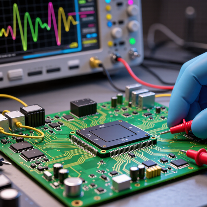
Choosing an analog-to-digital converter starts with the signal, not the resolution number on a data sheet. Write down the source type, voltage range, bandwidth, and whether the signal is single-ended or differential. A thermocouple produces a tiny, slow voltage; a motor-current shunt may produce fast transients beside electrical noise. They need different input ranges, filtering, and sampling rates. Small details matter.
Check the sensor’s output impedance and the converter’s input requirements. A mismatch can distort readings, even when the nominal voltage fits. Then estimate the smallest change you need to detect, and choose resolution with noise and effective number of bits in mind. Don’t confuse headline bits with usable precision. A first estimate is rarely perfect; leave margin, then verify it on the bench with the real sensor and wiring.
The application helps set the rest. The IEA’s Global EV Outlook 2024 reports nearly 14 million electric-car sales in 2023, about 18% of global car sales. Battery and motor systems illustrate why converter inputs must suit both slow measurements and rapid changes. WSTS reported worldwide semiconductor sales of $627.6 billion in 2024, up 19.1% from 2023, reflecting the scale of electronics across many applications. Those figures do not specify a converter, of course. For your design, also check channel count, sampling synchronization, isolation needs, operating temperature, and the digital interface. I would not skip a noisy-bench test. The quiet lab setup can be misleading.
An analog-to-digital converter (ADC) turns a changing voltage into numbers a processor can use. Its architecture affects speed, resolution, power use, and circuit complexity. Flash ADCs compare the input against many voltage thresholds at once, making them extremely fast. They suit brief, high-speed signals, but their component count and power draw can rise quickly. Successive-approximation-register (SAR) ADCs test bits one by one, narrowing the voltage range with each step. They often provide a practical balance for sensors and control systems. Speed costs power.
Pipeline ADCs divide conversion into stages, so they can process rapid signals with good throughput. Their latency may matter when timing is critical. Sigma-delta ADCs oversample the input and use digital filtering to achieve fine resolution, often for slowly changing signals such as temperature or pressure. They are less suited to very wide bandwidths. Not always. Compare the signal’s bandwidth and required resolution, then check latency, noise, and power against the full circuit. A quiet sensor on a long cable may need careful filtering more than a headline sampling rate. Specifications help, but real measurements can expose compromises. I’d verify performance with the actual source impedance and operating conditions; that step is easy to overlook.
| Tip | Converter Type | Operating Principle | Key Strengths | Trade-Offs | Typical Applications |
|---|---|---|---|---|---|
| 1. Match the conversion speed to your signal | Successive-Approximation Register (SAR) ADC | Uses a comparator and internal DAC to test digital codes one bit at a time, from the most significant bit to the least significant bit. | Offers a practical balance of speed, resolution, power consumption, and predictable conversion time. | Very high sample rates or very high resolution may require a different architecture; input settling and sampling behavior need consideration. | Data acquisition, control systems, portable instruments, and multiplexed sensor inputs. |
| 2. Prioritize low noise and high resolution for slower signals | Sigma-Delta ADC | Oversamples the input, shapes quantization noise away from the signal band, then uses digital filtering and decimation to produce output samples. | Can provide high resolution and strong in-band noise performance at low to moderate signal bandwidths. | Digital filtering introduces latency; the output data rate and usable signal bandwidth are lower than the internal sampling rate. | Precision measurement, scales, temperature sensing, audio, and low-frequency instrumentation. |
| 3. Choose a pipeline architecture for sustained high throughput | Pipeline ADC | Divides conversion into stages; each stage resolves part of the code and passes a residue to the next stage. | Supports high sampling rates while providing more resolution than is generally practical with a full flash architecture. | Pipeline stages add latency, and performance can depend on clock quality, calibration, and input frequency. | Communications receivers, imaging systems, and high-speed data acquisition. |
| 4. Use flash conversion when minimum latency matters most | Flash ADC | Compares the input simultaneously against a bank of reference thresholds using many comparators, then encodes the results. | Very fast conversion with extremely low conversion latency. | Comparator count grows rapidly with resolution, increasing circuit area and power; practical resolution is usually lower than in slower architectures. | Very high-speed signal capture, radar systems, and fast transient measurement. |
| 5. Favor integrating conversion for stable, low-frequency measurements | Dual-Slope Integrating ADC | Integrates the unknown input for a fixed interval, then applies a reference of opposite polarity and measures the time needed for the integrator output to return to zero. | Provides good accuracy and can reject periodic interference when the integration interval is chosen appropriately. | Conversion is relatively slow, so it is not suitable for rapidly changing signals. | Digital meters and precision measurement of slowly varying voltages. |
| 6. Consider a simple ramp converter when speed requirements are modest | Single-Slope (Counter-Ramp) ADC | A counter drives a DAC to create a stepped ramp; a comparator stops the count when the ramp reaches the input voltage. | Uses a straightforward conversion process and can be suitable where circuit simplicity is important. | Conversion time varies with input level and can be long; accuracy depends on the clock, DAC, and comparator behavior. | Simple, low-speed measurement circuits and educational demonstrations. |
| 7. For remote or noisy measurements, consider encoding voltage as frequency | Voltage-to-Frequency Converter | Produces an output pulse train whose frequency is proportional to the input voltage; a counter or timer measures the pulses to obtain a digital value. | Pulse signals can be convenient to transmit over longer distances and can be counted using simple digital hardware. | Requires a measurement interval to estimate frequency; conversion speed, resolution, and accuracy depend on the converter and counting method. | Remote sensors, isolated measurement links, and systems that already include pulse-counting inputs. |
Choosing an analog converter starts with the signal, not the largest number on a data sheet. Estimate the smallest voltage change your system must detect. A 12-bit converter divides its input range into 4,096 steps, but noise may hide several of them. Check effective resolution under realistic conditions, including the sensor, wiring, and input circuitry. More bits can add cost without revealing more useful detail.
Sampling rate should capture the signal’s fastest meaningful changes. For a 1 kHz waveform, sampling above 2 kHz is a theoretical minimum, not always a sensible target. Filtering, phase needs, and sudden transients can call for extra margin. If several channels share one converter, check whether the quoted rate applies per channel or to all channels combined. Small detail. Big difference.
Accuracy involves more than resolution. Review offset error, gain error, integral nonlinearity, reference stability, and drift across the expected temperature range. A converter may have fine step size yet still report a biased voltage. Compare the total error budget with your system’s tolerance, then test a known input at several points across the range. It is easy to over-specify on paper and miss a weak reference or noisy ground in the prototype. That deserves a second look.
An analog converter must match the signal it receives and the system around it. Start with the signal. Record its minimum and maximum voltage, whether it is single-ended or differential, and how quickly it changes. A sensor producing 0–2.5 volts, for example, may not use the converter’s full input range. That wastes resolution. Check input impedance and common-mode limits, too; a mismatch can distort readings before conversion even begins.
For an analog-to-digital converter, compare resolution, sampling rate, and noise performance with the measurement task. A fast sampling rate alone is not enough. If the signal contains higher-frequency components, an anti-aliasing filter may be needed. For a digital-to-analog converter, check output range, settling time, and the load it must drive. Small mismatches matter.
IoT Analytics’ State of IoT—Spring 2024 estimated 16.6 billion connected IoT devices at the end of 2023, with 29 billion projected by 2030. More connected sensors make careful signal-chain choices increasingly important.
Then check the system details: supply voltage, logic levels, communication interface, pinout, and operating temperature. Confirm that the converter works with the processor’s voltage levels and available interface; similar-looking parts may not be interchangeable. Measure at the pin. Review the full circuit, including reference voltage, grounding, and cable length, since these can affect accuracy. A datasheet may look reassuring, yet actual board noise can change the result. Test with the real sensor and load before committing to a design.
Choosing an analog converter starts with the power budget, not just the resolution printed on a specification sheet. Check supply voltage, peak current, and what happens during startup. A battery-powered sensor may tolerate a slower conversion rate to save energy, while a control loop may need stable sampling under load. Measure power on the actual board; other components can change the result. Small details matter.
The operating environment can shift performance. Heat may increase drift, while vibration, moisture, or electrical noise can affect readings and reliability. Compare the converter’s rated temperature range with the conditions inside the enclosure, not only the room temperature. Leave margin for hot afternoons and crowded circuit boards. A quiet lab is not the whole story. One useful check is to compare readings across expected temperatures and supply levels before committing to a design.
Cost includes more than the unit price. Consider external filters, voltage references, calibration time, and the cost of redesign if a part becomes unavailable. Review the manufacturer’s documentation, lifecycle notices, evaluation tools, and technical support options. Clear guidance can save hours when a circuit behaves oddly. Still, documentation is not proof that every application will work; test the converter with your signal source and layout. It is easy to overlook support until a project needs it.
