Choosing a Pressure Control Valve in 2026 starts with the process, not the product catalog. Record the inlet and outlet pressures, flow range, fluid properties, temperature, and expected operating changes. A valve that performs well at one steady flow may struggle during startup or peak demand. Small details matter. A pressure gauge that pulses, a line that whistles, or a downstream pressure that drifts can point to different sizing or control problems. Greg McMillan, a process-control expert, is often associated with this useful reminder: “The control valve is the muscle of the process control system.” For pressure service, that muscle must be sized and selected for the actual job.
This guide examines sizing, pressure drop, valve characteristics, materials, actuator choice, and failure position. It also considers noise, cavitation, maintenance access, and how the valve will respond when operating conditions change. Compare the required flow range with the manufacturer’s sizing data, and confirm assumptions with a qualified application engineer. Do not rely on nominal pipe size alone. That shortcut can be tempting. It is not enough. No worksheet captures every plant condition; field measurements and operating history may reveal gaps in the original assumptions. A careful selection should explain both what the valve is expected to control and where its limits lie. That is a less tidy answer, perhaps, but a more useful one.
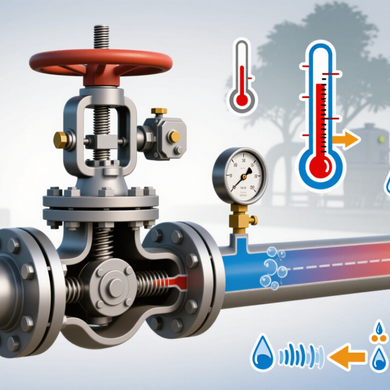
A pressure control valve keeps downstream pressure within a usable range as flow or inlet pressure changes. In a steam line, it can prevent pressure swings that affect heating equipment; in a hydraulic circuit, it helps protect hoses and actuators from excessive pressure. The valve is only one part of the system. Poor sizing, a blocked sensing line, or a badly placed pressure gauge can undermine its performance. Small details matter.
The U.S. Department of Energy’s Improving Compressed Air System Performance sourcebook reports that compressed air can account for about 10% of industrial electricity use. A pressure control valve does not eliminate that energy demand, but stable pressure can help avoid unnecessarily high setpoints. Actual savings depend on the system. That is easy to overlook.
Tips: Record normal and peak flow, inlet pressure, and the required outlet range before selecting a valve. Check the medium, temperature, pressure rating, and response needs against the application. Leave room for maintenance access. Then verify pressure at the point of use under changing demand, not only during a quiet test. A valve that looks right on paper may still need adjustment onsite.
A pressure control valve should be selected from measured system needs, not a line size alone. Record the required inlet and outlet pressures, normal flow, peak flow, and acceptable pressure variation. Include startup, shutdown, and other brief operating changes. A valve that performs well at steady flow may behave poorly during a sudden demand spike.
Describe the fluid carefully: gas or liquid, temperature range, viscosity, and any solids or corrosive components. These details affect valve materials, trim, and sizing. Small details matter. Check the available pressure drop across the valve at both minimum and maximum flow; too little differential pressure can limit control, while excessive pressure reduction may create noise or wear. Do not rely only on nominal pipe dimensions. Measure, don’t guess.
Define the control goal and response expected. Is the valve maintaining downstream pressure, upstream pressure, or another process condition? Note the required accuracy, response speed, and what should happen if power or instrument air fails. Review the actual operating data with the system designer or a qualified valve specialist, especially when conditions vary widely. Early estimates are useful, but they are not a substitute for verified measurements. A missing peak-flow value is a common weak point; flag it rather than treating it as certain.
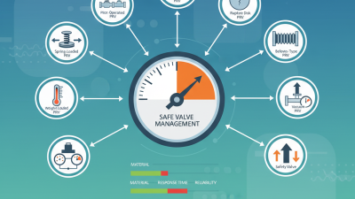
Pressure-control valves differ in what they hold steady. A pressure-reducing valve maintains lower downstream pressure; a back-pressure valve protects an upstream process by releasing flow when pressure rises. Direct-acting designs are compact and respond quickly, but changing inlet pressure or flow can shift their setpoint. Pilot-operated valves offer tighter regulation across wider flow ranges, though their small pilot passages need clean, compatible process fluid. Small details matter. The International Energy Agency’s Energy Efficiency 2023 report estimates that industry used about 37% of global final energy in 2022. That figure is not a valve-savings estimate; it shows why stable pressure and reduced process losses deserve careful attention.
Control configuration matters as much as valve type. A self-operated valve uses process pressure directly, avoiding external power and instrumentation. An actuated valve paired with a pressure transmitter and controller can support remote setpoint changes and tighter process integration, but adds wiring, calibration, and failure modes. For a steam line, for example, check the required downstream pressure during startup, not only at steady load. Size the valve using actual minimum and maximum flow, fluid properties, and pressure drop; IEC 60534-2-1 provides standardized sizing methods for control valves. One detail is easy to overlook: oversized valves may hunt at low flow, even when their catalog range appears adequate. Compare response, rangeability, maintenance access, and failure position against the real operating envelope.
How to Choose a Pressure Control Valve in 2026?
Valve sizing starts with the full operating range, not just the normal flow rate. Record minimum, typical, and maximum flow, inlet and outlet pressures, temperature, and fluid properties. Then use the sizing method in ISA 75.01.01 / IEC 60534-2-1 to estimate the required flow coefficient. A valve selected only for peak demand may be oversized and respond poorly at low flow. Small changes can matter.
Material and pressure ratings deserve equal attention. Check the body, trim, seals, and connections against corrosion, temperature, and possible erosion. ASME B16.34 pressure-temperature tables, for example, list 285 psi at 100°F for a Group 1.1, Class 150 steel valve. This is not a universal limit: material group, temperature, and the applicable standard edition affect the rating. Confirm the weakest component in the assembly, not just the valve body. The first selection is rarely the final one; real operating data may change it.
Tips: Compare the valve’s rated capacity with minimum and maximum demand. Ask for the pressure-temperature rating table and sizing calculation. Check what happens during startup, too. That detail is easy to miss.
| Selection Factor | Information to Confirm | Practical Selection Guidance | Common Pitfall to Avoid |
|---|---|---|---|
| Control function | Whether the valve must reduce downstream pressure, maintain upstream pressure, or provide overpressure protection. | Use a pressure-reducing regulator to control downstream pressure; a back-pressure regulator to maintain upstream pressure; and a code-compliant relief or safety valve for protective overpressure service. | Do not treat a pressure regulator as a substitute for a required safety or relief device. |
| Fluid and operating conditions | Fluid composition, phase, flow rate, normal and extreme temperatures, minimum and maximum inlet pressure, and required outlet pressure. | Provide operating cases—not just normal conditions—including startup, shutdown, turndown, and credible pressure extremes. Identify contamination, solids, viscosity, and corrosive components. | Choosing a valve from line size alone can result in poor control, excess noise, or inadequate capacity. |
| Valve sizing | Minimum, normal, and maximum required flow; pressure drop available across the valve; fluid properties; and allowable noise or velocity limits. | Size using the applicable manufacturer or engineering method for the fluid and operating conditions. For incompressible liquids, a common US-unit relationship is Q = Cv × √(ΔP/SG), where Q is in US gpm, ΔP is in psi, and SG is relative to water. | Gas and vapor sizing requires compressibility and choking considerations; the liquid Cv relationship is not suitable for gas sizing. |
| Valve and connection size | Required capacity, pipe schedule, end connection, installation space, and applicable piping standard. | Select the valve size from calculated capacity and operating range, then verify that the body and connections match the piping design. A valve may be smaller than the adjoining pipe when properly engineered. | Matching nominal pipe size does not establish that the valve has the correct capacity or controllability. |
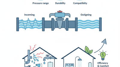
| Pressure range and stability | Desired set-point range, inlet-pressure variation, downstream demand variation, and allowable pressure deviation. | Choose a regulator whose documented control range covers the set point and expected flow range. Review droop, lock-up, sensitivity, and response for the actual service. | A set point within the adjustment range does not by itself guarantee stable or accurate control at every flow rate. |
| Pressure rating | Maximum allowable working pressure for the body, bonnet, trim, actuator, and connected accessories at the design temperature. | Verify the complete assembly against the applicable pressure-temperature rating and governing code. For flanged components, an ASME pressure class is not a single pressure value; allowable pressure depends on material and temperature. | Do not equate a nominal pressure class or set pressure with the allowable operating pressure at all temperatures. |
| Differential pressure and shutoff | Maximum and minimum pressure drop, pressure across the closed valve, and required leakage performance. | Confirm that the selected design and actuator can operate against the maximum differential pressure and meet the specified seat-leakage class or shutoff requirement. | Body pressure rating alone does not confirm actuator thrust, operating capability, or seat tightness. |
| Body and trim materials | Fluid compatibility, corrosion risks, temperature, erosion potential, and applicable material specifications. | Carbon steel is common in many non-corrosive industrial services; stainless steel may suit some corrosive or clean services. Select trim, seals, and body materials for the specific fluid and conditions. | Material suitability cannot be determined from the fluid name alone; concentration, temperature, contaminants, and stress conditions matter. |
| Seals and soft goods | Compatibility with the fluid, minimum and maximum temperatures, decompression risk, and required leakage performance. | Check the documented temperature and chemical limits for each elastomer or polymer, including diaphragms, O-rings, and seat inserts. | Do not assume that a seal suitable for the process fluid is also suitable for cleaning agents or transient conditions. |
| Noise, vibration, and cavitation | Gas pressure ratio, liquid pressure drop, fluid velocity, piping layout, and acceptable sound levels. | Request a noise and cavitation assessment for severe service. Consider suitable trim, staged pressure reduction, or other engineered measures where calculations identify risk. | High pressure drop can cause damaging noise, vibration, cavitation, or flashing even when the valve meets nominal capacity. |
| Installation and maintenance | Flow direction, orientation, straight-run requirements, sensing-line arrangement, access, and maintenance provisions. | Follow the valve’s installation instructions, provide isolation and depressurization provisions as required, and ensure the sensing point represents the pressure being controlled. | Poor sensing-line placement or an incorrect flow direction can impair control and may create unsafe conditions. |
| Standards and documentation | Applicable jurisdiction, piping and pressure-equipment codes, required certifications, inspection, and documentation. | Specify the governing requirements and obtain pressure-temperature ratings, material records, sizing data, leakage information, and installation instructions for the selected assembly. | Requirements vary by application and jurisdiction; confirm current project and regulatory requirements rather than assuming one standard applies everywhere. |
Engineering note: Treat this table as a selection checklist, not a final design. Confirm sizing, materials, pressure-temperature limits, and safety requirements with qualified engineering personnel and the applicable codes for the installation.
How to Choose a Pressure Control Valve in 2026?
Verifying Compatibility, Safety, and Maintenance Needs
Start with the real operating envelope, not just the pipe size. Record minimum and maximum inlet pressure, required outlet pressure, flow range, temperature, and pressure fluctuations. Then check body and seal materials against the actual fluid. A seal that swells or hardens can cause drift, leakage, or sticking. Small details matter. Confirm the valve’s capacity at your expected flow; a unit that works at average demand may struggle during startup.
Safety depends on the whole installation. Verify the valve’s pressure and temperature ratings, failure behavior, and connection with any independent pressure-relief device. Applicable standards, such as ISO 4126 for overpressure protection, can guide system design, but they do not replace site-specific engineering review. The U.S. Department of Energy’s Improving Compressed Air System Performance sourcebook estimates that leaks can waste 20–30% of compressor output. Valve connections deserve inspection, though they are only one possible leak source.
Plan maintenance before purchase. Check whether technicians can reach adjustment points, isolate the valve, and replace wear components without dismantling nearby pipework. Ask for inspection intervals and clear test procedures. A pressure gauge upstream and downstream makes drift easier to spot. Keep compatible seals and filters available where downtime is costly. I would still verify performance under changing loads; catalog figures rarely capture every installation. A neat specification can miss a messy plant reality.